Welcome to DieMount
Your expert for polymer optical fibers (POF) and POF – systems

Applications for POF fiber optic sensors
POF fiber optic sensors can be designed as duplex or simplex systems, both as extrinsic and intrinsic sensors as shown in the overview. By means of some examples we show the concrete implementation.
Fiber optic measurement of the mechanical pressure on a POF

According to the overview, this measurement is an intrinsic sensor in the duplex method. A POF optical fiber is used as a sensor element and mechanically strained by pressure, which is to be measured optically. The pressure leads to an increase in optical attenuation in the POF, which is measured with a POF Link Analyzer via two POF cables connected to the POF end faces.
In cooperation with the Institut für Stahlbau der RWTH Aachen, Herrn B. Schaaf, a demonstrator has been developed within the innovation network SMART SHM. It allows to monitor silicone bonds in structural glass engineering using the hardware and software of the POF Link Anaylzer.
The video shows in real time how the POF Reflection Meter records pressure changes between two steel plates.
The sensor POF can be either a soft POF with PUR core (polyurethane) or a standard POF with PMMA core (polymethyl methacrylate) with 1mm or 0.5mm diameter. The specific application determines which fiber is more suitable in each individual case. By optimizing the conditions for launch and outcoupling, the sensitivity of the sensor system can be increased considerably. However, this is at the expense of the overall system attenuation.
POF vibration measurement with the POF Reflectionmeter
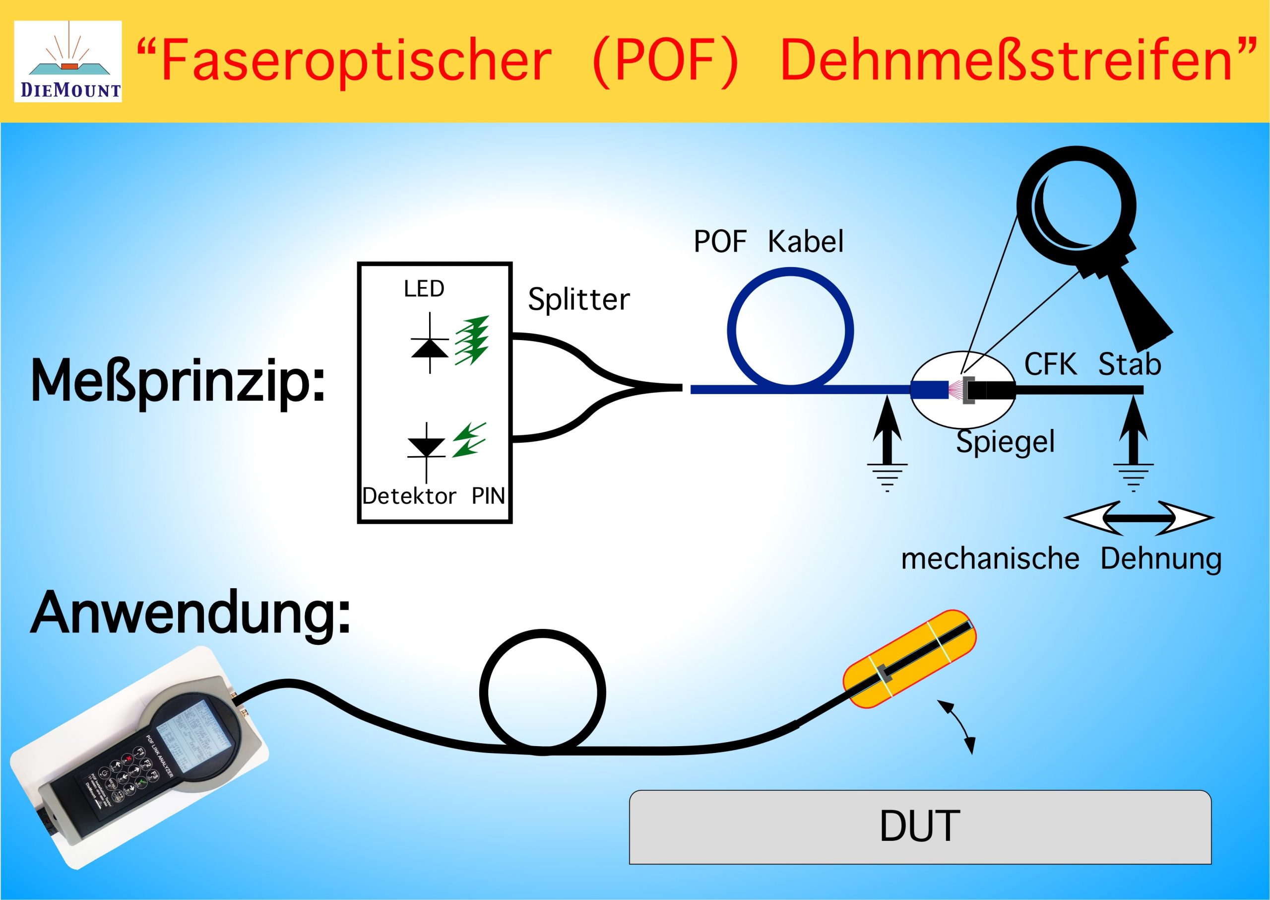
With an extrinsic simplex measurement method, the construction of a very interesting fiber optic sensor for the measurement of strains on machines and building elements with frequencies of up to 100Hz is possible. Vibration oscillations can thus be effectively detected by fiber optics. In a mechanically modified version, the method can be used to measure accelerations.
The POF Link Anaylzer is set up as a POF Reflectionmeter according to figure 3. A POF cable with the best possible end face preparation is connected to the 1×2 splitter of the instrument. At the end face of the cable in the sensor head there is a small movable mirror, which moves back and forth from the end face of the POF cable according to the strain to be measured. This creates a reflection that varies with the measured quantity, which is recorded by the POF Link Anaylzer.
With the POF Reflectionmeter, a simple sensor head for vibration measurement can be read out over distances of 100m and more using only one POF cable.
The POF Reflectionmeter for vibration measurement was presented for the first time at the International POF Conference 2015 in Nuremberg: Presentation Nuremberg 2015.
Further details, especially on the electronic and opto-electronic design of the sensor system, were subsequently shown at the International POF Conference 2017 in Aveiro, Portugal: Presentation Aveiro, 2017.
In order to demonstrate the suitability of the new measurement method in practical use for monitoring machines and building elements, cooperation with the specialists for SHM (Structural Health Monitoring), RWTH Aachen, Institut für Strukturmechanik und Leichtbau (SLA), was agreed in 2021.
Structural health monitoring (SHM) of many machines, plants and their components takes place under difficult EMI (electromagnetic interference) conditions. High currents, high electrical voltages or an explosive environment do not allow the use of classical electrical sensors. Wind energy plants endangered by lightning strikes and plants of heavy current or chemical process technology are examples.
The Institut für Strukturmechanik und Leichtbau (SLA), RWTH Aachen is pursuing the goals of the joint project:
- implementation of a fiber optic monitoring of structures based on the “polymer optical fiber” (POF) for the physical measurands strain and acceleration,
- optimization of the sensor layout and the measurement parameters with the aid of so-called structural damage indicators, which are carefully derived on the basis of structural-mechanical investigations,
- data integration of these parameters into the digital twin of the system,
- commercially attractive, i.e. cost-effective design of the entire SHM system comparable to conventional electrical sensor systems.
As a first result of the joint work, a comparison of classical, electrical strain gauges (DMS) with the POF strain sensor of DieMount created by SLA on the basis of a cantilever arm can be seen in the video here:
POF color measurement sensor
If the POF Link Analyzer is equipped with 3 LEDs of different colors and a 1×3 POF splitter as combiner according to figure 4, it can be used for fiber optic colour measurement. The basic principle is demonstrated in the video using a 650nm red, a 520nm green and a 460nm blue LED. A printed colour wheel is used as the wavelength selective reflector for the demonstration. The colours of the colour wheel are not optimally matched to the LED wavelengths, resulting in different intensities for the red, green and blue reflective signals. True-colour test objects and the exact matching of the LED to them correct this.
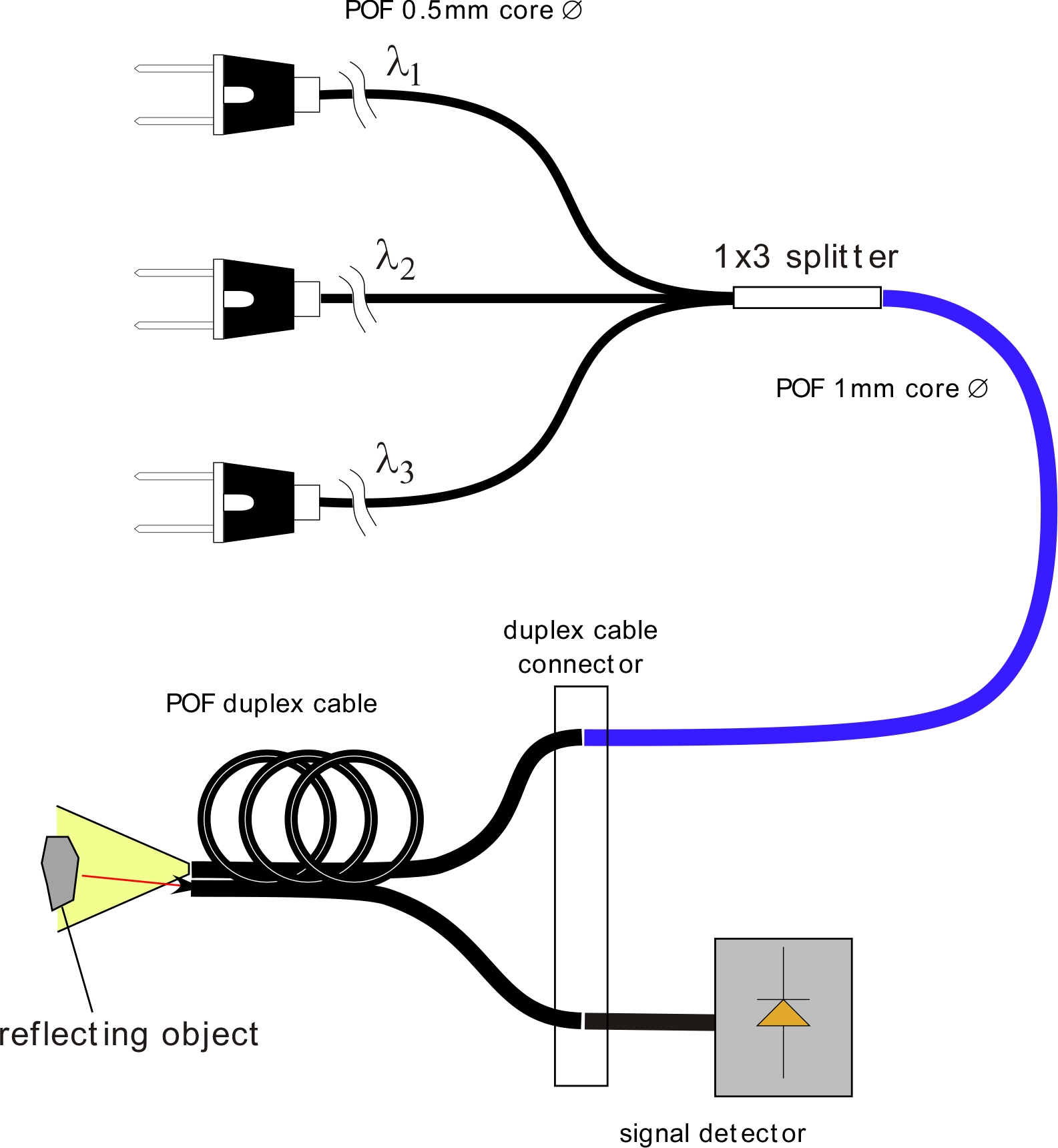
Fiber optic colour measurements are also interesting in the technical, chemical or medical field, if the wavelength of the LED is selected in such a way that the colour change caused by a physical process (rust formation on steel, colour change due to a change in the pH value or oxygen concentration of the blood due to red colouration) is measured. When selecting the LED wavelengths, attention should be paid to the attenuation spectrum of the PMMA POF.
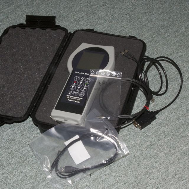
Qualification of home networks with the POF installation tester
The POF Link Analyzer in the POF Installation Tester version is used to qualify POF networks. After the installation of POF cables in a home network, the installer must provide verification by measurement that the cables he has installed meet the specified quality characteristics. In particular, it must be shown that
- an installed POF cable has a sufficiently low attenuation for the power budget of the optical transmission system, and
- that the optical signal power at the cable end is sufficiently high for the receiver.
The developed “POF Installation Tester” supports the installer in performing this task. For details on the use of the device see:
Instructions for attenuation measurement of POF cables with duplex connection cable.
Instructions for reflexive attenuation measurement of POF simplex cable