Welcome to DieMount
Your expert for polymer optical fibers (POF) and POF – systems

Devices for sensor technology: the POF Link Analyzer and its variants
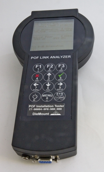
Design and function of the optoelectronic measuring unit "POF LINK Analyzer"
For fiber optic measurements a device is needed which contains the required LED light sources, the optical receivers, the serial connection to a PC and the control of the functional units as well as a pre-signal processing. The “POF Link Analyzer” has been developed for this purpose as a laboratory device. Thanks to its flexibly designed hardware, the device allows configuration for various measurement tasks (see applications for POF sensors), reading of the measured values on a display even without a PC, and also mobile use in battery operation. The device is insensitive to external light, i.e. daylight or artificial lighting have no influence on the measured value.
The microcontroller in the POF Link Analyzer can drive up to 3 LED light sources, read 2 sensitive receive channels with a dynamic range of 60dB (transimpedance 30kOhm) and a monitor channel of lower sensitivity (3kOhm). In the current version, the POF Link Analyzer reads out signal changes with a frequency of 100Hz; thus, a measured value is determined and output every 10ms. For easier display of the measured optical signals, the value output is in the unit dB referred to a reference value set at the beginning of the measurement. (The characteristics described here are defined in the software of the device and can be changed for a customer specific OEM version).
The electronic structure with the possible options in the POF Link Analyzer is shown in figure 1:

In the device, 3 fiber-coupled LEDs are provided as optical sources, which are driven with an operating current of max. 50mA. The wavelength of each LED is selectable.
A frequently used variant is a measuring device for 2-channel attenuation measurement. If required, LED 1 can be equipped with a green LED (520nm) and LED 2 with a red LED (650nm) in order to have the two wavelengths most commonly used in POF applications available in one device.
The POF Link Analyzer for 2-channel attenuation measurement is available from DieMount as a standard product in the version with 2 green LEDs (part no. 04020303).
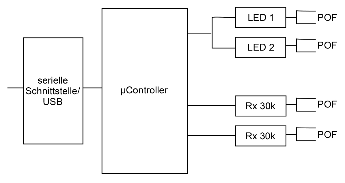

Figure 3 shows the POF Link Analyzer in the POF reflection meter version. A low crosstalk splitter is integrated in the device to measure the reflection of the transmitted signal on a single outgoing POF cable. This avoids the additional losses that occur with an externally mounted splitter. On the page Applications for POF sensors the details of this use case are presented in more detail.
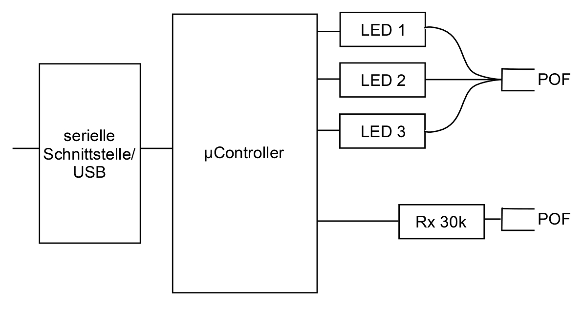
Figure 4 last shows the design of the POF Link Analyzer as a fiber optic colour measuring instrument. Each of the 3 LEDs has a different wavelength (e.g. red, green and blue, but any other color combination is also selectable) and radiates into the POF cable via a 1 x 3 splitter. The receiver detects each wavelength separately. Thus a statement can be made about the spectral reflection factor of the object illuminated by the POF. Fiber-optically, a colour is measured in this way.
For measurement tasks that require a high attenuation of more than 50dB measurement, it is useful to increase the transmit power to the maximum possible limit. An example is the attenuation measurement with mode-selective fiber launch and outcoupling (see application POF sensors). Instead of an LED with max. 50mA current, a PowerLED with 200mA can be used. This is connected to the POF Link Analyzer via an electrical connector. The PowerLED module has an optical connector to connect the POF cable. However, since the receiver would not be functional due to saturation, if the PowerLED module were directly coupled , the reference value (zero calibration) must be set with the highly attenuating cable connected. In addition, eye safety precautions must be taken into account.